Saturday 24 December 2016

Quantel Schematics & Documentation

During my adventures with the Quantel Paintbox i have unearthed several pieces of documentation that i have scanned in and provided on my Google Drive for all to access.

Many Quantel products used the 3U V-Series chassis so these documents maybe of relevance even to non Paintbox systems. For example the Editbox used the same architecture as the V-Series but was in the larger rack.

As i add more i will include the details into this post

To access the repository use this link:

The current list of documents is as follows:

Quantel BridgeProcessor2 2058-66 Schematic.pdf
Schematics for the Bridge Processor used in the V-Series chassis.

Quantel CPU3 2060-74 Schematic.pdf
Schematic for the 68010 CPU3 (2060-74) card used in the early V-Series chassis.

Quantel CPU42 2078-82 Schematic.pdf
Schematic for the 68040 CPU42 (2078-82) card used in the later V-Series chassis, similar 2099 & 2101 boards were also used in the Editbox, Domino systems that used the same architecture.

Quantel DiskStore1M 2060-72 Schematic.pdf
Schematic for the DiskStore1M (2060-72) card used in many of the V-Series chassis.

Quantel VideoOut4 2057-69 Schematic.pdf
Schematic for the VideoOut4 (2057-69) used in some of the V-Series chassis, this has YUV/RGB analog and SDI digital output.

Quantel Netcom & Snetcom Documentation.pdf
Some possibly internal user guide for the Netcom and Snetcom board used in the V-Series chassis.

Quantel Network Engineering Training Manual 2066-58-050B.pdf
Network Engineering Training Manual 2066-58 for the V-Series including details of picturenet etc.

Quantel Paintbox Express Installation Manual 2090-58-030B.pdf
Complete installation manual for the Paintbox Express, this is a later 68040 based V-Series machine.

Quantel Paintbox Maintenance Training Manual 2056-58-050C.pdf
Some maintenance & engineering information for the V-Series Paintbox.

Quantel Picturebox Maintenance Training Manual 2057-58-050C.pdf
Similar to the manual above but for the V-Series Picturebox.


Wednesday 7 December 2016

Quantel Paintbox V-Series - Setting The RTC Date

EDITED 25-10-2017: Since this was written i have found there are built in commands for setting the RTC located in the diagnostics console at \FILER\UTILITIES\TIME. However the details here still apply if you wish to set the RTC manually. Note the RTC located on Netcomm or Snetcomm boards is located in a different memory location (base at $F30000) but operates in the same way.

I have recently been playing around getting a Quantel Paintbox (V-Series Harriet) running. During the process i had to replace the battery backed SRAM which also contained the Real Time Clock (RTC).

Within the Paintbox user interface there is an option to set the time but not the date, this is even true in the engineering console where you have more access to the operating system. The only way to set the date is to manually set the RTC clock by poking bytes into a memory location.

This is due to Quantel's time-limited software keys. If there was an easy way to set the date then it would be easy to circumvent their feature expiry time by simply adjusting the system date before the key expires.

The V-Series CPU3 (also CPU3, CPU42 & CPU43) board has two battery backed SRAMs, these are the ST MK48Z02 and the MK48T02. The 'Z' version is a regular SRAM, the 'T' version includes a RTC which is mapped into the last 8 bytes of the MK48T02's 2048 byte address space.

In the CPU3 implementation 'RF' (the component designation on the PCB silkscreen) is the MK48T02 and 'RD' is the MK48Z02. Both devices are memory mapped into the 68000 address space starting at $040000 to $040FFF. The MK48Z02 is mapped to EVEN bytes and the MK48T02 is mapped to ODD bytes to give a total capacity 4,087 bytes (accounting for the 8 RTC control registers).

According to the datasheet for the MK48T02 device the RTC register map is as follows:

Add  D7 D6 D5 D4 D3 D2 D1 D0
7FF:  -  -  -  -  -  -  -  - : Year 00-99
7FE:  0  0  0  -  -  -  -  - : Month 01-12
7FD:  0  0  -  -  -  -  -  - : Date 01-31
7FC:  0 FT  0  0  0  -  -  - : Day 01-07
7FB: KS  0  -  -  -  -  -  - : Hours 00-23
7FA:  0  -  -  -  -  -  -  - : Minutes 00-59
7F9: ST  -  -  -  -  -  -  - : Seconds 00-59
7F8:  W  R  S  -  -  -  -  - : Control

ST=Stop Bit
R=Read Bit
FT=Frequency Test
W=Write Bit
S=Sign Bit

KS=Kick Start Bit


To translate this to the Paintbox memory map we must multiply the address by 2 and add $40001. So the map becomes:

Add    D7 D6 D5 D4 D3 D2 D1 D0
40FFF:  -  -  -  -  -  -  -  - : Year 00-99
40FFD:  0  0  0  -  -  -  -  - : Month 01-12
40FFB:  0  0  -  -  -  -  -  - : Date 01-31
40FF9:  0 FT  0  0  0  -  -  - : Day 01-07
40FF7: KS  0  -  -  -  -  -  - : Hours 00-23
40FF5:  0  -  -  -  -  -  -  - : Minutes 00-59
40FF3: ST  -  -  -  -  -  -  - : Seconds 00-59
40FF1:  W  R  S  -  -  -  -  - : Control


You can poke bytes into these addresses using the Quantel AFS Monitor on the serial port prior to booting the Paintbox software or you can use the 'MEMORY' command from within the Paintbox console.

Using the AFS Monitor to set the date to Wednesday 7 December 2016, remembering the values are BCD and the year is defined as years since 1980.

At the command prompt:

Allow write access to registers & stop clock:
40FF1;80

Set the day of week:
40FF9;03

Set the date:
40FFB;07

Set the month:
40FFD;0C

Set the year:
40FFF;36

Disable write access to registers & start clock:
40FF1;00

Tuesday 22 November 2016

Teardown: AMO Sovereign Phaco - Cataract Surgery Machine

In this teardown i look at a AMO Sovereign WhiteStar Phaco machine used to perform cataract surgery.

'Phaco' is a short form of Phacoemulsification which uses an ultrasonic knife to cut into the eye and chop up the damaged lens into small pieces soa new artificial lens can be inserted.

The machine i acquired was used in a local vets almost complete but with without the ultrasonic hand tools. Probably they kept them as spares for their new machine which replaced this one.

The machine is made up of a steel and aluminium chassis and the control box mounted on the top. Inside the chassis is an air pump, motorised IV pole, printer, storage tray and the along with the foot switch a few other electrical cables and power distribution.

The main controller is made from a steel outer chassis with plastic coverings. Mounted on the front is a LCD screen and control buttons. Inside the controller is a switch mode power supply, Ziatech embedded computer, phaco and diathermy power control board, parastaltic pump and valve arrangement and a SCSI solid state drive which contained the operating program.

The embedded computer is a Ziatech Z200, this uses a 80486DX4-100 CPU with 8mb RAM with several option boards; SCSI 2 Interface, Soundcard, fluidics controller and phaco controller.

A thanks and shoutout to Mike of MikesElectricStuff for tipping me off about this item which was local to me. Thanks Mike!


Saturday 5 November 2016

Teardown: Kodak CR500 Computed Radiography X-Ray Scanner

In this video i begin looking at a Kodak DirectView CR500 Computed Radiography scanner.

A computed radiography system exposes special x-ray plates in regular x-ray equipment but the image is not stored photographically. It's stored in special materials on the imaging plate.

To reveal the image stored on the plate it's digitally recovered using a CR Reader, which is what the Kodak CD500 is. The cassette is offered up the the machine where it extracts the imaging plate from the cassette, scans a red laser over the plate which makes the material fluoresce blue. The blue light is picked up using photomultiplier tubes and then digitised and processed so the image can be viewed on a computer.

The imaging plate is then exposed to bright visible light to erase it for re-use. 


Part 1: Disassembly of the main components.


Part 2: Looking closer at the main components.

Friday 5 August 2016

Dallas DS12887A NVRAM PC CMOS External Battery Hack

If you have ever dealt with vintage electronics you'll know the feeling when you see a self-contained NVRAM battery module installed into whatever it is. Is the internal battery exhausted? Will the device still operate without it even if it's replaced?

Well this time it was the turn of a Shuttle HOT-433 motherboard dating from around 1997 and it featured a Dallas DS12887A RTC and NVRAM module.  Thankfully being a PC motherboard they are tolerant of a battery failure so i should be able to replace the module and we'll be up and running again.


But then i thought, i know these Dallas RTCs have been hacked open before to gain access to the internal battery so i thought i'd give this one a go and see if i could get the board back up and running without waiting for a new DS12887A to arrive in the post.

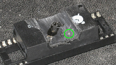
So the first procedure was to desolder it and prepare it for surgery, here it is inserted into a IC socket to protect the pins and i have already begun to file down the top of the case to find the battery.


After more filing i eventually revealed one of the battery terminals.


At this stage i also noticed a second terminal just showing through the potting compound circled here in green. Measuring across the large terminal and this small terminal i found 1.2v of a very flat 3v lithium cell.

The next step i broke off the two small welds that attach the large negative battery terminal to break the connection to the internal battery, allowing me to wire in a new connection to an external CR2032 battery clip.

After this was done i installed a socket to the motherboard to allow easy future replacement of the DS12887A RTC.


Once installed the motherboard of course required me to reset the clock and CMOS settings and now the motherboard is working perfectly again.

One that was done and everything proved to be working i applied hot-glue to protect the wires and we're done!


Friday 20 May 2016

Examining & Repairing A Quantel Paintbox Part 1

The Quantel Paintbox was a set of custom hardware and software that revolutionised the video and TV production industry throughout the world in the 1980s and 1990s. Allowing easy and fast graphics to be produced for broadcast.

Developed by a UK company Quantel the Paintbox went through a number of revisions, the hardware was a custom design based on the Motorola 68000, most of the graphical features were realised in hardware.

I was offered one of the 2nd generation machines dating from 1989 codenamed 'Harriet'. Part of the V-Series of hardware the Harriet was a fully loaded system featuring optional hardware for 3D perspective shaping of graphics and video capture to a large internal RAM store called the Ramstore. Cost at the time of production was around £65,000.

Quantel Paintbox Harriet

The system is modular, in that there is a backplane which cards are plugged into. Exactly which boards are supplied with the base system and which are optional i am not sure yet. Certainly the main CPU board and video output boards would be standard, in the Harriet there are also the Perspective, Main Store, Main Store 2 and Video Input boards.

The system as i received it included the base unit, keyboard, tablet, pen & cables. Complete with the exception of the 'Rat' which was like a mouse.

My system is currently non-functional, the CPU board is fairly sophisticated however and has some diagnostic features and details the fault as a Bus Error.

The Harriet uses a Motorola 68010 CPU running at 10Mhz, there is a small amount of ROM which stores the bootloader and a CPU monitor, this bootstraps the main operating system from an internal 5.25" SCSI drive.

The Monitor application has a RS232 output port which has a menu and diagnostic features easily accessible with an appropriate terminal application on another computer.

Bus Errors on the 68000 CPU are monitored by external circuitry that asserts the BERR line on the CPU when no data returns on the bus when requested. A simple binary counter is used in the Paintbox clocked from the main oscillator. When the counter reaches a certain point one of the binary outputs asserts the BERR line through an inverter. As memory is accessed and data returned it continually resets the counter, unless there is a fault. When a BERR occurs the CPU jumps to the exception vector for the BERR and executes code there.

In part 2 i will detail more of my investigation...

Friday 6 May 2016

Sony Betacam Dynamic Tracking Video Heads

During the teardown of a Sony BVW-75 Betacam SP VCR (which dates from 1988) i was delighted to see it used a system called dynamic tracking on the video heads, this is an interesting technology so i am going to take a quick look at how it might be working in this example.

Tracking in video tape machines is an important factor in image quality, in a helical scan tape format the heads must follow precisely the path of the signal else deterioration of the signal will occur.

Methods for controlling this are not simple as timing is critical to get the head which is rotating on the drum to meet the track just at the right time and place.

Dynamic Tracking takes a real time correction approach to this problem. By including additional heads onto the drum which scan and read the the video track just before the actual video heads arrive allows the system to servo the heads to the correct location in real time.

In the picture below you can see the heads on the base of the video drum of this Betacam machine. There are a total of 10 heads.


The two single heads are the rotary erase heads used when recording onto the tape. There are two pairs of fixed read heads on the far left and right of the image and two pairs of read heads that can be moved vertically. The pair of movable video read heads are the larger ones mounted on a separate subframes.

I propose the two pairs of fixed heads are the dynamic tracking read heads, i would expect these to be slightly offset vertically from each other so they should track just above and below the signal on the video tape.

If the tracking is perfect the signal from these heads should be equal, but if there is an offset between them this can be detected and the movable video heads can be adjusted up or down to compensate for the offset in time for the video read heads to scan the tape.

The movable heads are operated by piezoelectric elements driven by i believe a +/- 250v supply generated away from the drum in a separate power supply module.

The video read heads are located on the end of a sandwich of two piezo elements which is the light gold coloured plane in the picture below. This is mounted on a small aluminium frame for support. The connections to the heads run down a flat flex cable just above the piezo element and a number of connections run to the piezo element. The actual video heads can be seen glued to a metallic element which itself is glued to the piezo element.


Close-up Of One Of The Video Heads.


There are a number of connections to the piezo element as i believe this has two elements, one to move the head up and one to move the head down. In the picture below you can see the video heads at the far left, the piezo element is the dark grey area above the aluminium frame and the head signal wires are contained in the flat-flex cable suspended above it.


Top down view of the Dynamic Tracking Video Heads.


Sunday 17 April 2016

Teardown: Sony BVW-75P Betacam SP VCR

In this video i teardown a Sony BVW-75P Betacam SP video recorder & edit deck. The Betacam SP format dates from 1986 but this machine is slightly later and dates from 1988.

The Betacam format, introduced in 1982 is an evolution of the consumer Betamax video tape format that was introduced in 1975 and was aimed squarely at professionals and the broadcast industry.

This BVW-75P is a PAL version Betcam SP edit deck, with playback, record and editing functions.

The Betacam SP format has 340 lines of resolution with 4.5Mhz of Luminance and 1.5Mhz of Chrominance video bandwidth.

The system also uses a mechanism called Dynamic Tracking, which is to allow accurate tracking of the video tape signal using Piezoelectric elements which move the video heads vertically in real time to match the tracking of the video tape it's playing.


Part 1


Part 2


Part 3


Monday 4 April 2016

Windows 7 WUAUSERV With High CPU & No Windows Updates

I have several PCs in my 'lab', a couple of laptops and two desktops. Of these one laptop and the two desktops run Windows 7 Professional. They are all fully licensed.

My main PC is working fine thankfully but both my laptop (a Sony Vaio from around 2011) and my 'spare' PC are suffering from high CPU load from WUAUSERV. This is actually the Windows Update service which provides automatic updating of security updates.

Thankfully both these machines are not turned on much and i have spent almost zero time to figure out what's wrong with them until now when i have tried to rid myself of these Windows Update issues.

My spare desktop used to be my main PC, it's a little old and decrepit it used to run Windows XP but i upgraded due to the EOL issues with XP. It's Windows 7 Professional 32bit.

As it had been my main PC i thought best thing i can do is just wipe it and re-install windows from scratch.

So this is what i did, the only remaining disk in the system was erased and Windows 7 reinstalled from new from the DVD.

After the usual installation of the odd driver i let windows pull down all the necessary windows updates since the creation of my install disk (Win7 SP1), which it did. Some updates installed and some failed. This is in fact normal in the first run of updates. After each reboot it would pick up a few more as dependences and pre-requisites for the updates change as they are installed.

This is where my issues arrived...

After the last run of updates i found the CPU hovering at 50% usage and the updater seems to be frozen checking for updates. The process is SVCHOST.EXE running WUAUSERV as shown in this screenshot:


I have 172 updates now installed on the system and is probably quite up to date right now (April 2016) but it's stuck now so i wont be seeing any new updates going forward. All i get now is 50% CPU load all the time and the Windows Update dialog shows only the following and never completes an update.


Now this issue is not new, indeed Microsoft have a couple of utilities available to diagnose problems like this. These are the Windows Update Troubleshooter and KB947821 aka System Update Readiness Tool (SUR).

The Windows Update Troubleshooter clears the Windows Update cache, logs etc and also checks a number of things that cause issues with updates.

The System Update Readiness Tool does some magic, to be honest i have no idea what it's doing but i think it goes deeper into checking for problems as it's a 200Mb+ installation compared with Windows Update Troubleshooter which is only a few 100Kb.

Both of these were run with no luck, SUR always exits with no reports so i have no idea what it may have looked for, found or tried to fix. The troubleshooter does have a report at the end which details it's unable to fix error 0x800F081F.

Looking around for this error shows it has a plethora of solutions meaning it's probably some generic failure mode without a specific cause. It is interesting though that this was a clean and freshly installed system. My only conclusion is this is caused by one of the updates arriving by the Windows Update mechanism.

I will continue my quest for a resolution and report back when i have some news.

Monday 1 February 2016

Brandenburg 628-10 10KV Power Supply Teardown

I recently picked up two of these Brandenburg Gamma Series power supplies. A 628-10 (10kV at 10mA) and a 728-10 (20kV at 5mA).

The 628-10 here produced no output but the 728-10 did but has some minor issues. The output HV connector plug was missing, the earth HV return post was broken and was generally a bit grubby.

So i opted to cannibalise the non working 628-10 for it's internal Brandenburg Type 37 HV connectors and a couple of other minor components and scrap the rest.

I expect to be testing and later selling on the 728-10 unit.


Wednesday 6 January 2016

DER EE DE-5000 LCR Meter Kelvin Clip Conversion Hack


I recently purchased a DER EE DE-5000 LCR meter, these are well regarded and inexpensive meters made in Taiwan. The unit i purchased was supplied with the TL-21 test leads that plug into the banana sockets and test ports to provide easy to use clips for testing components.


Although the meter is great i was a little disappointed with the test leads, although they are kelvin to the crocodile clip they are very short and dont supply a proper kelvin connection to the component. The two connections are terminated at the solder point on the crocodile clip. So i wanted to change this so i had some proper kelvin probes which had longer wires and easier to use clips.


I was not looking for the ultimate in performance, but just to improve the usability and performance for a reasonable price so i chose to buy a cheap set of kelvin clips off ebay, these cost about £10 including shipping from china. The set i bought was supplied with BNC connectors and coax. This i thought should be ideal for retrofitting into the existing TL-21.

The kelvin clips i bought from ebay.


On opening the DER EE TL-21 test leads, i was pleasantly surprised to find 4 wires running to the crocodile clips and the guard/screen in place which meant converting them with the cheap kelvin clips a simple task.


The BNC connectors were chopped off the new clips and the cable shortened to about 30cm, these were simply soldered in place of the original clips.


After running the calibration (zeroing) procedure on the meter with the new leads, shorting the clips shows 0.00 ohms, it's a shame DER EE dont offer these as an accessory.