Saturday, 19 September 2015

Magstim 200 Hacked: Charging & Triggering Success!

So it's taken a couple of months to figure this Magstim 200 out and i have finally made it charge, trigger and discharge the capacitor.

After my last blog entry where i had disabled the 'Replace Coil' error / interlock by brute-forcing the PAL (Programmable Array Logic IC that seems to control the final safety interlocks to find the correct combinations that would disable the lock, this worked but left me with the device unable to trigger.


The PAL IC on the breadboard along with a binary counter IC (Motorola MC14060B) 
to run through all the 512 combinations of logic inputs to find the state that would disable the 'Replace Coil' error.

You can see on the scope picture above the top trace is the 4th stage counter output to the PAL, the other stages connect to each of the other PAL input pins so it will cycle through every combination as the counter (a Motorola MC14060B) counts upwards. The 2nd lower trace is the output pin that controls the replace coil error, so this is showing there are only two input states that bring the coil error output low indicating a fault.

Note there is a total of 512 output states from this PAL IC but not all the input pins will be applicable to this output condition. Clearly you can see there is only a few input states that control the output which is why there is only 9 clock cycles before the pattern repeats.

I simply clocked the counter first at high speed (a 100khz or so) watching the output on my oscilloscope in roll mode to first check the coil error state does change, then slow down the clock (to just a few hz) so i can stop it when it's in the output condition i want. I can then read off the state of the inputs. This can then be compared to the states seen when the IC is in the actual magstim board when the error is showing. In my case pin 5 was low and should be high. Disconnecting the input pin from it's source and bringing it high removes this lock.


Bodge wire from VCC to pin 5, this should be pulled high to disable the interlock. The bodged on resistor is from the factory!

I also look at the charge voltage of the capacitor, i see a maximum reading of around 1700v, this is less than i expected. In the documentation i have seen from Magstim it indicated it would be around 2800v as seen in this excerpt from "Guide to Magnetic Stimulation" by Reza Jalinous:-


Full video after removing the interlock:


I spent much time tracing the trigger circuit, and found the front panel board supplies 5v to the trigger input of the potted trigger block. This is pulled low by the front panel trigger button only when pin 'K' on the front panel connector is also pulled low to ground.

This pin would be for the interlock switch located on the Magstim coil itself, intended to be held in by the operator when they are ready to trigger the device. So typically they would place the coil where they wanted, hold in the coil interlock and then either press the front panel 'Trigger' or depress a pneumatic foot switch to actually trigger the unit.

So a simple fix, once this was discovered i could remove the multi-way connector from the front panel and solder a bridge wire across those pins on the front panel board.


Bodge wire to remove the coil switch interlock.

In the future i will make some binding posts for the front panel to allow easy connection and disconnection of things i want to blow up or experiment with.

So currently the unit will charge the capacitor to about 1700v in 1% steps. I have done some measurements of this and found the accuracy of this is very approximate and certainly at the higher charges the charge leaks away requiring the unit to keep topping up the capacitor. At the higher voltages the hysteresis of this can be as much as 40v or so. At the moment i am not sure if this self discharge is natural leakage in the capacitor or other parts of the circuit.

At 100% the capacitor is charged to about 1680v so has about 268 Joules of energy stored. The lowest power (1%) will charge the capacitor to about 40v which is 0.15 Joules. The scaling of the % power value to the actual voltage is non-linear, certainly at power levels below 30%. Upto 30% it is much better, at 30% the charge will be about 525v which is actually closer to 10% of full power. Above the 30% the power does rise in more linear fashion to 100%.

The capacitor seems to measure 190uF and is oil filled. Magstim rated the capacitor to a minimum 200,000 full charge cycles. Quite impressive for what it does. I would expect the capacitor was a significant part of the BOM for this device along with the Thyristor. The capacitor i believe is a General Atomics DP Series 39504 which are general purpose pulse capacitors capable of upto 25kA. The 39504 is rated at 185uF at 3000v.

I have also noticed that the mechanical counter only counts when its triggered at over 80% power.

Power Levels vs Voltages vs Joules
1% = 40v = 0.152 Joules
25% = 425v = 17.1 Joules
50% = 850v = 68.6 Joules
75% = 1,275v = 154.4 Joules
100%  = 1,680v = 268.1 Joules

Full video after i resolved the triggering issue:

Friday, 28 August 2015

Magstim 200: HV Charging & Control Boards

Following the teardown of the Magstim 200 TMS device i featured on my youtube channel a few weeks ago i have been slowly de-potting the two (what i call) bricks.

The two devices seemed to control the charging and discharging of the main HV capacitor in the device. Although i could infer their purpose i did want to explore further.

The first brick to get some treatment was what appeared to be the charging brick, firstly i used a hot air gun, this seemed to work well initially by softening the potting compound but the effect only went a few mm deep but it did reveal some components.

Thanks to a couple of comments about how to better remove the potting compound i ordered a litre of Dichloromethane, removed as much of the external packaging as much as i could and immersed them.

After a just hours the first brick softened and i was able to remove enough of the compound to discover it's operation.

The connections across the top are 240v AC IN from the supply mains, which is switched through two Solid State Relays operated by the main control board. The output is fed to the primary of the HV transformer.

The secondary of the HV transformer runs through a set of external power resistors and back into the HV AC IN of the charging brick where there is a bridge rectifier consisting of 8 discrete diodes. The output of the rectifier runs through 4 power resistors to supply rectified HV to the remaining connector on the power brick (HV DC OUT).


The other brick which i see as the charging & triggering brick is more complex with 6 connections, it was potted with a different material and took much longer to come off, i wasn't able to remove all of it as i ran out of dichloromethane but it was enough to see what each of the connections did. The High Voltage DC from the charging brick connects to two connections and also pass through to the main HV capacitor. The positive is internally connected through two 30MOhm resistors to what i suspect will be voltage monitoring feeding back to the main control board. The negative side of the High Voltage DC seems to connect internally to the SCR switching outputs. The final connection is clearly a low voltage input control from the main control board. It took over three weeks in Dichloromethane to reveal this.

Saturday, 25 July 2015

Teardown: Magstim 200 TMS Transcranial Magnetic Stimulator Base Unit

In this video i disassemble a Magstim 200, this is a TMS device manufactured in the late 1980s. Production began in the mid 1980s and ran through until at least 1999.

TMS is a medical technique to stimulate the brain and nerves throughout the body using a closely coupled induction coil placed on the head that is energized with a short duration high voltage/high current pulse. The magnetic field from the coil induces small currents into the brain or nerves through the skull and skin.

The Magstim Company was founded from research performed at Sheffield University during the early and middle 1980s.

I recently purchased two used Magstim 200 base units for teardown. One appears to be working and dates from the late 1990s, the other is broken and dates from the late 1980s. It's the broken one i teardown in this video.


Saturday, 11 July 2015

Repairing An M5 Thread On A Capacitor

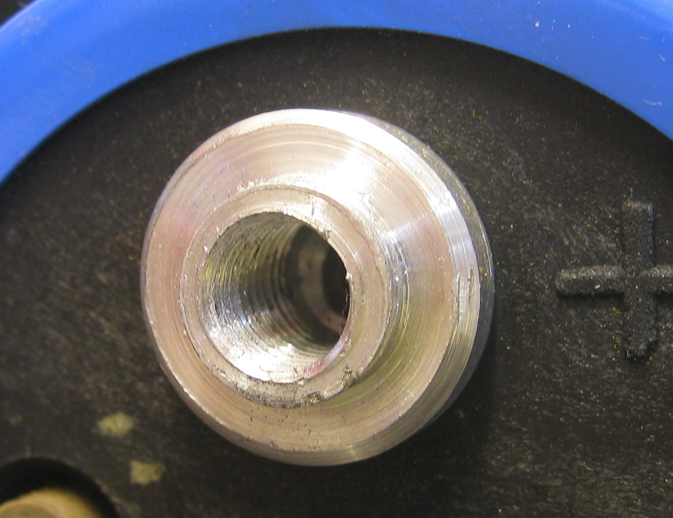
I salvaged four capacitors from the Red Light Camera i did a teardown on a while ago. I found when i removed them that one capacitor had one thread completely gone. It looks like it might have just been over tightened at the factory.

The damaged thread.

I opted to try and Helicoil it, i have used them before to repair larger threads like M12, the capacitor uses two M5 which are much smaller but i thought i would give it a try.

The procedure involves buying a kit which contains the coils, drill, tap and a couple of insertion tools.

The first step is to drill out the old thread with the included drill bit then you tap and then insert the coil. The coil becomes the new thread at the original size.

In this instance there is a small issue in that these are not really designed to be inserted into shallow blind holes, you need enough depth to get the drill in and the tap has to work to a minimum depth to cut the thread.

So first off i ground the tip off the drill and the tap so i can work with a shallow hole.

Drill and Tap with ground ends.


After drilling out the old thread.


Cutting the new thread with the supplied tap.


The new intermediate thread for the coil.


The coil on the insertion tool. The coil will become the new M5 thread.


Inserting the coil. It simply screws in.


The end result, a new M5 thread that will actually be stronger than it was originally.

Saturday, 4 July 2015

Midland G9 PMR446 5 Watt Full Power Export Modification

In this article i will detail how to convert a normal Midland G9 Plus or G9E Plus 2-way radio to the export version that has enhanced 5 watt output. It also allows the two PTT buttons to be used to operate the radio in standard 500mW and in 5000mW.


The modification is quite simple on this 2015 version Midland G9E Plus.


Take your Midland G9 and remove the belt clip and batteries. You will find four screws located in the battery area and one next to the belt clip. Carefully remove these with Philips screwdriver.


Open the cover carefully, note the wires to the vibration motor, these can easily be broken if they are pulled hard.


At the top of the PCB next to the On/Off/Volume control you will find three jumper links labelled J-1, J-2 & J-3.

To make the modification, simply cut links J-2 & J-3. 

The radio can be re-assembled. When you next turn on the power the settings will reset to factory default.

The radio will operate as it did before but with the exception that the PTT & PTT Boost will work differently. In the menu if you change PRL setting to be 'L'. This will make the PTT button transmit at 500mW and the PTT Boost button will transmit at 5000mW.

Other Notes:

The radio seems to be operated by a Beken BK4811 transceiver IC.

Power consumption measurements at 5.00v
Idle: 78mA
Idle + Backlight: 95mA
TX 100mW: 170mA
TX 500mW: 470mA
TX 5000mW: 980mA

I also made some measurements of the battery level indicator:
Full battery indication at 4.77v+
2 bar battery indication at 4.72v
1 bar battery indication at 4.5v
Bat Lo warning at 4.3v