Friday, 28 August 2015

Magstim 200: HV Charging & Control Boards

Following the teardown of the Magstim 200 TMS device i featured on my youtube channel a few weeks ago i have been slowly de-potting the two (what i call) bricks.

The two devices seemed to control the charging and discharging of the main HV capacitor in the device. Although i could infer their purpose i did want to explore further.

The first brick to get some treatment was what appeared to be the charging brick, firstly i used a hot air gun, this seemed to work well initially by softening the potting compound but the effect only went a few mm deep but it did reveal some components.

Thanks to a couple of comments about how to better remove the potting compound i ordered a litre of Dichloromethane, removed as much of the external packaging as much as i could and immersed them.

After a just hours the first brick softened and i was able to remove enough of the compound to discover it's operation.

The connections across the top are 240v AC IN from the supply mains, which is switched through two Solid State Relays operated by the main control board. The output is fed to the primary of the HV transformer.

The secondary of the HV transformer runs through a set of external power resistors and back into the HV AC IN of the charging brick where there is a bridge rectifier consisting of 8 discrete diodes. The output of the rectifier runs through 4 power resistors to supply rectified HV to the remaining connector on the power brick (HV DC OUT).


The other brick which i see as the charging & triggering brick is more complex with 6 connections, it was potted with a different material and took much longer to come off, i wasn't able to remove all of it as i ran out of dichloromethane but it was enough to see what each of the connections did. The High Voltage DC from the charging brick connects to two connections and also pass through to the main HV capacitor. The positive is internally connected through two 30MOhm resistors to what i suspect will be voltage monitoring feeding back to the main control board. The negative side of the High Voltage DC seems to connect internally to the SCR switching outputs. The final connection is clearly a low voltage input control from the main control board. It took over three weeks in Dichloromethane to reveal this.

Saturday, 25 July 2015

Teardown: Magstim 200 TMS Transcranial Magnetic Stimulator Base Unit

In this video i disassemble a Magstim 200, this is a TMS device manufactured in the late 1980s. Production began in the mid 1980s and ran through until at least 1999.

TMS is a medical technique to stimulate the brain and nerves throughout the body using a closely coupled induction coil placed on the head that is energized with a short duration high voltage/high current pulse. The magnetic field from the coil induces small currents into the brain or nerves through the skull and skin.

The Magstim Company was founded from research performed at Sheffield University during the early and middle 1980s.

I recently purchased two used Magstim 200 base units for teardown. One appears to be working and dates from the late 1990s, the other is broken and dates from the late 1980s. It's the broken one i teardown in this video.


Saturday, 11 July 2015

Repairing An M5 Thread On A Capacitor

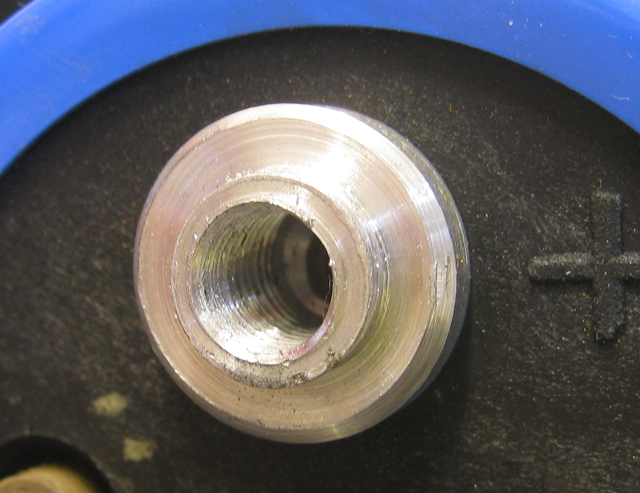
I salvaged four capacitors from the Red Light Camera i did a teardown on a while ago. I found when i removed them that one capacitor had one thread completely gone. It looks like it might have just been over tightened at the factory.

The damaged thread.

I opted to try and Helicoil it, i have used them before to repair larger threads like M12, the capacitor uses two M5 which are much smaller but i thought i would give it a try.

The procedure involves buying a kit which contains the coils, drill, tap and a couple of insertion tools.

The first step is to drill out the old thread with the included drill bit then you tap and then insert the coil. The coil becomes the new thread at the original size.

In this instance there is a small issue in that these are not really designed to be inserted into shallow blind holes, you need enough depth to get the drill in and the tap has to work to a minimum depth to cut the thread.

So first off i ground the tip off the drill and the tap so i can work with a shallow hole.

Drill and Tap with ground ends.


After drilling out the old thread.


Cutting the new thread with the supplied tap.


The new intermediate thread for the coil.


The coil on the insertion tool. The coil will become the new M5 thread.


Inserting the coil. It simply screws in.


The end result, a new M5 thread that will actually be stronger than it was originally.

Saturday, 4 July 2015

Midland G9 PMR446 5 Watt Full Power Export Modification

In this article i will detail how to convert a normal Midland G9 Plus or G9E Plus 2-way radio to the export version that has enhanced 5 watt output. It also allows the two PTT buttons to be used to operate the radio in standard 500mW and in 5000mW.


The modification is quite simple on this 2015 version Midland G9E Plus.


Take your Midland G9 and remove the belt clip and batteries. You will find four screws located in the battery area and one next to the belt clip. Carefully remove these with Philips screwdriver.


Open the cover carefully, note the wires to the vibration motor, these can easily be broken if they are pulled hard.


At the top of the PCB next to the On/Off/Volume control you will find three jumper links labelled J-1, J-2 & J-3.

To make the modification, simply cut links J-2 & J-3. 

The radio can be re-assembled. When you next turn on the power the settings will reset to factory default.

The radio will operate as it did before but with the exception that the PTT & PTT Boost will work differently. In the menu if you change PRL setting to be 'L'. This will make the PTT button transmit at 500mW and the PTT Boost button will transmit at 5000mW.

Other Notes:

The radio seems to be operated by a Beken BK4811 transceiver IC.

Power consumption measurements at 5.00v
Idle: 78mA
Idle + Backlight: 95mA
TX 100mW: 170mA
TX 500mW: 470mA
TX 5000mW: 980mA

I also made some measurements of the battery level indicator:
Full battery indication at 4.77v+
2 bar battery indication at 4.72v
1 bar battery indication at 4.5v
Bat Lo warning at 4.3v


Sunday, 28 June 2015

Archiving Hi8 Video Tapes to MP4

So recently i was reading up about the Hi8 Video tape format, this is what i used to use back in the 1990s and 2000s with my Sony TRV-66E camcorder.

I have a significant amount of old tapes that never get played and read that the Hi8 tape format is prone to degradation after about 15 years.

So with that in mind i began to transfer my tapes into H.264 / AAC streams for proper archiving and uploading to YouTube, so these are my experiences.

Tape Degradation
I have viewed some of my tapes and some do show some form of playback artefacts. As you can see in this picture below the bottom half is affected by distortion and horizontal sparkle effects and runs throughout the entire tape. Visually there is nothing visible on the physical tape itself.


Digitizing The Media
This is a lossy step in the process, that means you can affect the quality of the final recording depending on how you do this.

I dont have a PC based video capture device, it's not something i have needed before. I have used them in the past (during the late 1990s and early 2000s) with mixed results, maybe better products are out there now but i generally dont like them!

I do however, have a decent quality hard disk based DVR and DVD writer (a Sony RDR-HX710). This will allow me to record my tapes into an MPEG2 stream either directly onto a DVD+R or to the internal HDD for later transfer to DVD+R.

The DVR can accept analog video in the forms of composite or  S-Video. S-Video is obviously the preferred format here as it separates parts of the video signal to retain more detail.

Because the DVR has only a single layer DVD writer i am limited to standard 4.7Gb DVD+R or DVD+RW so i need to try and fit one whole Hi8 tape onto one DVD. I want to make the 90 minutes fill the disk. If you encode the tape so it only fills 1/3 of the DVD your effectively losing quality because you may find a slightly high recording quality in the DVR settings that could fill the disk with nothing left over.

After some testing i found the most efficient way to record the tapes was to write DVD+Rs directly. This saves me time as there is no HDD -> DVD recording process. I also found using the DVR quality setting on 'HSP' (this is only a Sony naming convention, yours may be different). This encodes at about 7.7 Mbps.


Using the DVR is great, it means i can set play/record and leave it to finish,  it doesn't tie up my PC for hours and i don't have to worry about wonky capture device drivers that will drop frames if you so much as look at the PC the wrong way, or audio that drifts out of sync. It also means i can just archive my tapes onto many DVDs that can be ripped and edited at a later date. In addition to this the output is pure PAL standard 720x576 25FPS Interlaced.

Transferring to PC
This part should have been the simplest, but in reality it was not but in a way it helped the process in a funny way.

After the DVD is written and finalised i can take the DVD and read off the files on my PC. All DVDs are readable this way with the exception of copyright protected disks that have their files encrypted. Because this is an original recording from my DVR there is no encryption so the files can be copied without any issue.

The files that contain the actual content are the VTS_01_[X].VOB located in the VIDEO_TS folder. Copy and rename these on the PC to .MPG and they will play in most media players.

This is where i hit my first problem, for some reason the first VOB file wont play in VLC or load into Movie Studio. It's corrupt or badly formed in some way. It plays fine on the DVR and in Windows Media Player. Thankfully it does load into Handbrake. I have transferred recordings using this method before without issue so i may look into this further to see which bit i'm doing is causing the problem.

I wanted to edit and make the final videos from this original MPEG2 source in Movie Studio but there was a lot of noise in the encoding, small MPEG blocking artefacts and high frequency noise from the original tape and i had this issue with the corrupt file. Movie Studio has little or no options for removing blocking artefacts or noise too so i needed another solution...

After some experimenting i found i could encode these MPEG2 streams into MPEG4 using Handbrake which can read the corrupt file and apply some additional processing to reduce some of the artefacts so in a way it helps even though it adds an additional encoding step and more time to the process. So my handbrake settings were as follows:

Picture Tab: 

Anamorphic: Strict
Cropping: custom, set to zero. Handbrake does a poor job of cropping and i prefer to use the pan/scan options in Movie Studio. So i disable this option, annoyingly it will always revert back on any new video.


Filters Tab:
Deinterlace: Fast, being an original PAL source the picture is interlaced so  this should be removed prior to encoding into the final video.
Deblock & Denoise: Off

Video Tab:
Quality: 12
Constant Framerate: On
Framerate: Same As Source
x264 Preset: Medium
x264 Tune: Grain
H.264 Profile: High

Alternative Method, less filtering, lower compression.
This method i disable the deblock and denoise functions and increase the compression Quality enough so the inherent grain is retained. This actually looks more natural. There is a balance though, you need enough quality to resolve the noise. Not enough and the noise will turn into very obvious blocking itself. In my tests a Quality setting of 12 and disabling the deblock and denoise functions.

Final Differences
I was going to include some half and half images between the MPEG2 and MP4 versions but the differences are so subtle i doubt you would be able to see them. It really is just some high frequency noise.

Editing
The original MPEG2 .VOB files are around 1Gb in size, after conversion to MP4 they do increase to more than 2.5Gb, i found this was inevitable to retain the grain, this is only an intermediate format for editing though. Once the videos have been rejoined, edited, cropped and some basic level and gamma correction they are exported from Sony Movie Studio as a 5mbps MP4.