Wednesday, 7 March 2018

Hacking A Quantel Dylan Disk Array

I have recently been working on a Quantel HAL video compositing system as featured on my last post.

While i have been trying to diagnose all it's faults i discovered a rather annoying feature of the Dylan disk array that stores the video clips.

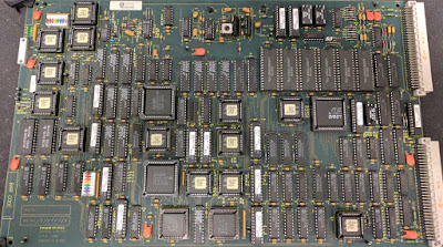
The array is a 6U chassis that contains three PCBs with a controller CPU and 20 SCSI disk controllers to operate the 20 Fujitsu hard disks.

During my work the Dylan flagged up one of the disks had failed but continued to work, shortly after it then flagged another and disabled video from the array.

Once this happened i tried replacing a disk only to be met with a 'disk serial changed' message, i tried swapping the replacement disk into one of the slots for a working disk which generated another disk serial changed error and the array now had three drives that were not working.

At this point i realised that either the host system (Quantel HAL) or the array was keeping a track of the disk drive serial numbers and preventing replacement of the disks. After some investigation i found no details of the disk serial numbers within the HAL operating system so looked at the array itself.

The CPU on the array is an Inmos / ST Micro IMST425-G25. This is a 25mhz Inmos 'Transputer', further examination of the control board didn't show up any EPROM for holding the program for this CPU but it did show up an Inmos link IC. The link IC allows a host to load CPU code over a serial link through the CPU to RAM and then start the CPU. Basically meaning the code is loaded remotely by the HAL.

So there was no EPROM or battery backed SRAM on the controller, the task now was to find where the serial numbers were stored.

After careful examination of the board i found a Atmel 24C02 serial EEPROM. This was de-soldered using hot-air, mounted into a test clip and read out using a TL866 EPROM reader/programmer.


Immediately it was clear it contained the serial numbers of the disk drives with three of them containing zeroed serial numbers, very likely the three drives that had been flagged up previously. The remaining serial numbers were exact matches for the serial numbers printed on the physical disks.

From here it was a simple task to add the missing and new serial numbers into the EEPROM and reprogram it. I also added a plug in board to allow this to be done easier next time.


It's highly likely that Quantel engineers had a tool to program in new serial numbers into the array through a 10 pin header located on the PCB.

Quantel HAL Video Compositing System - Introduction

The Quantel HAL is an evolution of the V-Series architecture that Quantel introduced in the late 1980s as used originally on the 2nd generation Paintbox, it expands on it with upto 18 plugin expansion cards on it's expanded backplane (Hiway as Quantel call it) housed in a 6U chassis.

The Quantel HAL system is a video compositing system that can composite upto 99 'layers' in a single pass. Layers would be static images, video clips or stencils (masks) that can all be manipulated in a 3d space along with various effects that can be applied. Video storage is on a separate 'Dylan' disk array connected via a proprietary interface and contains 24gb of disk storage to give a total of 15 minutes of uncompressed standard def PAL/NTSC video.

In many ways it's similar to the Quantel Harriet, which is a combination of a Paintbox and Ramcorder. The Harriet is designed for compositing static pictures and animation on top of video and is limited to 323 frames in the Ramcorder. The HAL differs in it has far greater storage and can composite video on video with key (stencil) channels on any of the 99 layers.

The user places video clips, pictures and stencils onto a keyframe timeline to create a sequence of effects which are then rendered out to a new clip or composited over the top of an existing clip.

The main chassis contains two hard disks, a system boot disk and a shared disk. The boot disk contains all the software and local files, the shared disk contains all the network shared files. This setup is exactly the same as the Paintbox. There are 4 SDI video inputs and outputs, 1 (stereo) digital audio input and 2 outputs along with an analog 'broadcast standard' video in/out.


Side View of the HAL showing all the cards.
The PSU and two hard disks are mounted in the top.


The Dylan disk array contains 20 fujitsu 1.2gb 3.5" SCSI disks each with it's own SCSI controller a lot of logic and a small Inmos/ST transputer CPU to look after the array. There is no CPU code stored on the array as it's loaded over a dedicated 'inmos link' when the main system boots. The array CPU simply looks after errors from the disks. From what i understand the HAL writes video round-robin to the disks. There is ECC so the data on a failed drive can be rebuilt once it's replaced. The array also stores the disk serial numbers of the drives in an EEPROM to prevent user-replacement of the disks. If a disk is changed the system will flag the disk and stop using it. Once two disks are either flagged as serial number changed or have found to be faulty the array will go offline and the user is unable to have access to video on the HAL. The capacity of the array is determined by the software keys on the HAL system, so probably all disk arrays had 24gb but depending on how much ££ you paid quantel you could have access to 5, 10 or 15 minutes of video.


Top view of the Dylan 2 disk array. The Inmos CPU is in the top left corner, PSU in the middle and the SCSI controllers around the edge with the cables running to the disks.


HAL System cards:
The HAL contains the usual 3 cards found in any v-series system. CPU, Mainstore, Diskstore and some kind of image processing card like is found in a Paintbox. So this could be Size, Rotation, Perspective, CAP (Contour and Perspective) or Image. With Image being the most advanced.

CPU: Quantel's standard CPU42 board with 64mb RAM & 68040 CPU.


Netcomm: Quantel's standard netcom board, 68000 based network interface.


Input Select: Analog video input processing card and digital video input (the actual digital input decoding is processed on a smaller board located in the top of the chassis).


APE: Audio processing card.


Image: Essentially a software CPU / processing engine based on a large quantity of altera CPLDs and an Inmos/ST Transputer CPU, provides all the processing for image transforms (size, rotation, 3d effects etc).


Diskstore: Regular diskstore card.


Mainstore: Regular mainstore card.


Output Select: Analog video output processing & digital video output (the actual digital output decoding is processed on a smaller board located in the top of the chassis).


Mux: interface to the dylan disk array.


Disk Link: I think more disk array interface stuff.


Router: I think this does some switching of video to/from the disk array.


Key 2: lots of logical processing on this card, going by it's name it must be something with video keying.


Vid Proc 2: like Key 2 this has lots of 'bit-twiddling' ICs for image processing.


Thursday, 12 October 2017

Inside A Toyota GT86 Ignition Coil Pack

Some pictures of the insides of a Toyota Ignition Coil Pack from a Toyota GT86.

This particular coil pack failed which seems to be a common problem on the GT86. I decided to see how they are constructed to see if there was any sign of why this one failed.

It sat in Dichloromethane for about two months to remove the potting compound and plastics. Occasionally i would take it out and remove some of the softened plastic and immerse it again.

Although the depotting process has caused significant damage to it we can see the major components.

A coil pack is basically a pulse transformer, there is an iron core with the high voltage secondary coil wound around and separated into sections, this is to provide isolation between the sections of the coil as the coil will generate many 10s of kilovolts. The primary winding can't really be seen but the thicker gauge wire is visible slightly at the top connected to the outer most conductors at the top.

Also visible is a diode and under the main connection terminals is the driver IC (a black rectangle) which has four connections. These connect to the external 3 contacts which provide GND, +12v and Trigger inputs, the fourth connection on the IC is the other side of the primary winding.

The spark plug connection has departed from the secondary coil as it was connected only to the fine wires of the secondary, it fell off during the depotting process.

Interestingly the driver IC does seem to be cracked, it's not clear though if this was caused by me during depotting or if it is the cause of the coil pack failure.


The coil pack before depotting.

The three external connections are on the right, with the driver IC just under them.

View of the high voltage secondary.

Top view showing the external connections and the IC underneath.

Friday, 19 May 2017

Teardown: Photec IV - 20,000 FPS 16mm Film Camera

In this video i take a look inside a 1980s film camera capable of 20,000 FPS.

The Photec IV camera was introduced in the 1980s by Photonic Systems Inc, It is a high speed 16mm movie film camera that uses a rotating prism to allow the film to run through the camera in a continuous motion.

The camera can take 400 ft film loads and has a Mamiya 645 lens mount.

The camera was available in different configurations, different prisms could be installed for full frame, half frame and quarter frame shooting which multiplied the FPS by x1, x2 and x4. The configuration on my camera is half frame.

The camera has a configurable FPS from 100 to 1000 FPS in 100 FPS steps and 1,000 to 10,000 FPS in 1,000 FPS steps at full frame. In half frame configuration this is 200-20,000 FPS and quarter frame is 400-40,000 FPS.

Mechanically they are quite simple, a large motor drives the take up reel, the action of the film running through the sprockets drives the prism.

At 10,000 FPS the linear film speed is around 170mph.


Saturday, 11 February 2017

Reading Unsupported PROMs On A MiniPro TL866

As part of our slow progress with the Quantel DPB-7001 Paintbox we have been working a way to try and emulate a SMD hard disk. Because we don't have a working DPB or an SMD drive we need to build a rudimentary emulator of the disk controller element of the DPB so we can understand how it works.


Quantel DPB-7001 Disk Sequencer Card with 7 PROMs on the far right.

This will allow us to design a replacement plugin card for the physical DPB-7001 that would replace the Disk Sequencer card with a SMD emulator built into it using some flash memory and an FPGA.

Although most of the DPB uses standard 74 series logic, the disk controller uses an AMD AM2910 microcode sequencer driven from a small set of codes contained within 7 PROMs. We need to extract the code from these to be used within the DPB emulator that is being written. These PROMs are 28L22 devices with 256 x 8 bits of storage. The addressing is simple for these devices, there are 8 address lines to address each of the 256 memory locations and 8 data bits of output.

Unfortunately my MiniPro TL866 EPROM programmer doesn't support the 28L22, but that does not mean it can't read them with a bit of thought.

What we can do is make a small adaptor board to convert the pinout of the 28L22 PROM to be pin compatible with some other memory device the TL866 can read.

The closest match i could find was the AM2716B, which is a EEPROM with 2048 x 8 bits of storage. Though this has 10 address lines to access the additional memory space of this device. This is not a problem, we can simply leave these two extra address lines unconnected at the reader. The result of this is the reader will think it's reading out 2048 bytes of data but in fact it will be reading 256 but it will wrap around 8 times in the data readout.

Firstly we need to make an adaptor board to connect the device into the TL866:


During construction, the pin headers protrude through the base of the strip board to make contact with the ZIF socket of the TL866. Each pin can then be wired to a IC socket the 28L22 PROM will plug into.


View from underneath.


The 28L22 PROM plugged into the TL866.

Once the data is read out, we simply discard the last 1792 bytes of data to get to the original 256 bytes of data.