Tuesday, 22 November 2016

Teardown: AMO Sovereign Phaco - Cataract Surgery Machine

In this teardown i look at a AMO Sovereign WhiteStar Phaco machine used to perform cataract surgery.

'Phaco' is a short form of Phacoemulsification which uses an ultrasonic knife to cut into the eye and chop up the damaged lens into small pieces soa new artificial lens can be inserted.

The machine i acquired was used in a local vets almost complete but with without the ultrasonic hand tools. Probably they kept them as spares for their new machine which replaced this one.

The machine is made up of a steel and aluminium chassis and the control box mounted on the top. Inside the chassis is an air pump, motorised IV pole, printer, storage tray and the along with the foot switch a few other electrical cables and power distribution.

The main controller is made from a steel outer chassis with plastic coverings. Mounted on the front is a LCD screen and control buttons. Inside the controller is a switch mode power supply, Ziatech embedded computer, phaco and diathermy power control board, parastaltic pump and valve arrangement and a SCSI solid state drive which contained the operating program.

The embedded computer is a Ziatech Z200, this uses a 80486DX4-100 CPU with 8mb RAM with several option boards; SCSI 2 Interface, Soundcard, fluidics controller and phaco controller.

A thanks and shoutout to Mike of MikesElectricStuff for tipping me off about this item which was local to me. Thanks Mike!


Saturday, 5 November 2016

Teardown: Kodak CR500 Computed Radiography X-Ray Scanner

In this video i begin looking at a Kodak DirectView CR500 Computed Radiography scanner.

A computed radiography system exposes special x-ray plates in regular x-ray equipment but the image is not stored photographically. It's stored in special materials on the imaging plate.

To reveal the image stored on the plate it's digitally recovered using a CR Reader, which is what the Kodak CD500 is. The cassette is offered up the the machine where it extracts the imaging plate from the cassette, scans a red laser over the plate which makes the material fluoresce blue. The blue light is picked up using photomultiplier tubes and then digitised and processed so the image can be viewed on a computer.

The imaging plate is then exposed to bright visible light to erase it for re-use. 


Part 1: Disassembly of the main components.


Part 2: Looking closer at the main components.

Friday, 5 August 2016

Dallas DS12887A NVRAM PC CMOS External Battery Hack

If you have ever dealt with vintage electronics you'll know the feeling when you see a self-contained NVRAM battery module installed into whatever it is. Is the internal battery exhausted? Will the device still operate without it even if it's replaced?

Well this time it was the turn of a Shuttle HOT-433 motherboard dating from around 1997 and it featured a Dallas DS12887A RTC and NVRAM module.  Thankfully being a PC motherboard they are tolerant of a battery failure so i should be able to replace the module and we'll be up and running again.


But then i thought, i know these Dallas RTCs have been hacked open before to gain access to the internal battery so i thought i'd give this one a go and see if i could get the board back up and running without waiting for a new DS12887A to arrive in the post.

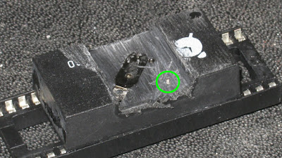
So the first procedure was to desolder it and prepare it for surgery, here it is inserted into a IC socket to protect the pins and i have already begun to file down the top of the case to find the battery.


After more filing i eventually revealed one of the battery terminals.


At this stage i also noticed a second terminal just showing through the potting compound circled here in green. Measuring across the large terminal and this small terminal i found 1.2v of a very flat 3v lithium cell.

The next step i broke off the two small welds that attach the large negative battery terminal to break the connection to the internal battery, allowing me to wire in a new connection to an external CR2032 battery clip.

After this was done i installed a socket to the motherboard to allow easy future replacement of the DS12887A RTC.


Once installed the motherboard of course required me to reset the clock and CMOS settings and now the motherboard is working perfectly again.

One that was done and everything proved to be working i applied hot-glue to protect the wires and we're done!


Friday, 20 May 2016

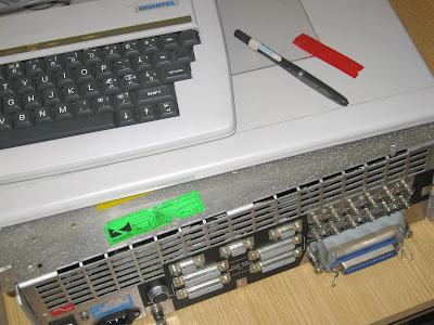
Examining & Repairing A Quantel Paintbox Part 1

The Quantel Paintbox was a set of custom hardware and software that revolutionised the video and TV production industry throughout the world in the 1980s and 1990s. Allowing easy and fast graphics to be produced for broadcast.

Developed by a UK company Quantel the Paintbox went through a number of revisions, the hardware was a custom design based on the Motorola 68000, most of the graphical features were realised in hardware.

I was offered one of the 2nd generation machines dating from 1989 codenamed 'Harriet'. Part of the V-Series of hardware the Harriet was a fully loaded system featuring optional hardware for 3D perspective shaping of graphics and video capture to a large internal RAM store called the Ramstore. Cost at the time of production was around £65,000.

Quantel Paintbox Harriet

The system is modular, in that there is a backplane which cards are plugged into. Exactly which boards are supplied with the base system and which are optional i am not sure yet. Certainly the main CPU board and video output boards would be standard, in the Harriet there are also the Perspective, Main Store, Main Store 2 and Video Input boards.

The system as i received it included the base unit, keyboard, tablet, pen & cables. Complete with the exception of the 'Rat' which was like a mouse.

My system is currently non-functional, the CPU board is fairly sophisticated however and has some diagnostic features and details the fault as a Bus Error.

The Harriet uses a Motorola 68010 CPU running at 10Mhz, there is a small amount of ROM which stores the bootloader and a CPU monitor, this bootstraps the main operating system from an internal 5.25" SCSI drive.

The Monitor application has a RS232 output port which has a menu and diagnostic features easily accessible with an appropriate terminal application on another computer.

Bus Errors on the 68000 CPU are monitored by external circuitry that asserts the BERR line on the CPU when no data returns on the bus when requested. A simple binary counter is used in the Paintbox clocked from the main oscillator. When the counter reaches a certain point one of the binary outputs asserts the BERR line through an inverter. As memory is accessed and data returned it continually resets the counter, unless there is a fault. When a BERR occurs the CPU jumps to the exception vector for the BERR and executes code there.

In part 2 i will detail more of my investigation...

Friday, 6 May 2016

Sony Betacam Dynamic Tracking Video Heads

During the teardown of a Sony BVW-75 Betacam SP VCR (which dates from 1988) i was delighted to see it used a system called dynamic tracking on the video heads, this is an interesting technology so i am going to take a quick look at how it might be working in this example.

Tracking in video tape machines is an important factor in image quality, in a helical scan tape format the heads must follow precisely the path of the signal else deterioration of the signal will occur.

Methods for controlling this are not simple as timing is critical to get the head which is rotating on the drum to meet the track just at the right time and place.

Dynamic Tracking takes a real time correction approach to this problem. By including additional heads onto the drum which scan and read the the video track just before the actual video heads arrive allows the system to servo the heads to the correct location in real time.

In the picture below you can see the heads on the base of the video drum of this Betacam machine. There are a total of 10 heads.


The two single heads are the rotary erase heads used when recording onto the tape. There are two pairs of fixed read heads on the far left and right of the image and two pairs of read heads that can be moved vertically. The pair of movable video read heads are the larger ones mounted on a separate subframes.

I propose the two pairs of fixed heads are the dynamic tracking read heads, i would expect these to be slightly offset vertically from each other so they should track just above and below the signal on the video tape.

If the tracking is perfect the signal from these heads should be equal, but if there is an offset between them this can be detected and the movable video heads can be adjusted up or down to compensate for the offset in time for the video read heads to scan the tape.

The movable heads are operated by piezoelectric elements driven by i believe a +/- 250v supply generated away from the drum in a separate power supply module.

The video read heads are located on the end of a sandwich of two piezo elements which is the light gold coloured plane in the picture below. This is mounted on a small aluminium frame for support. The connections to the heads run down a flat flex cable just above the piezo element and a number of connections run to the piezo element. The actual video heads can be seen glued to a metallic element which itself is glued to the piezo element.


Close-up Of One Of The Video Heads.


There are a number of connections to the piezo element as i believe this has two elements, one to move the head up and one to move the head down. In the picture below you can see the video heads at the far left, the piezo element is the dark grey area above the aluminium frame and the head signal wires are contained in the flat-flex cable suspended above it.


Top down view of the Dynamic Tracking Video Heads.